Energy monitor with optimizer for solar power consumption.
General description.
This energy monitor displays how much electric energy is going in or out of your house.
It displays a positive value if you use power from the mains.
And it displays a negative value when you export power into the mains (when you
have enough solar energy).
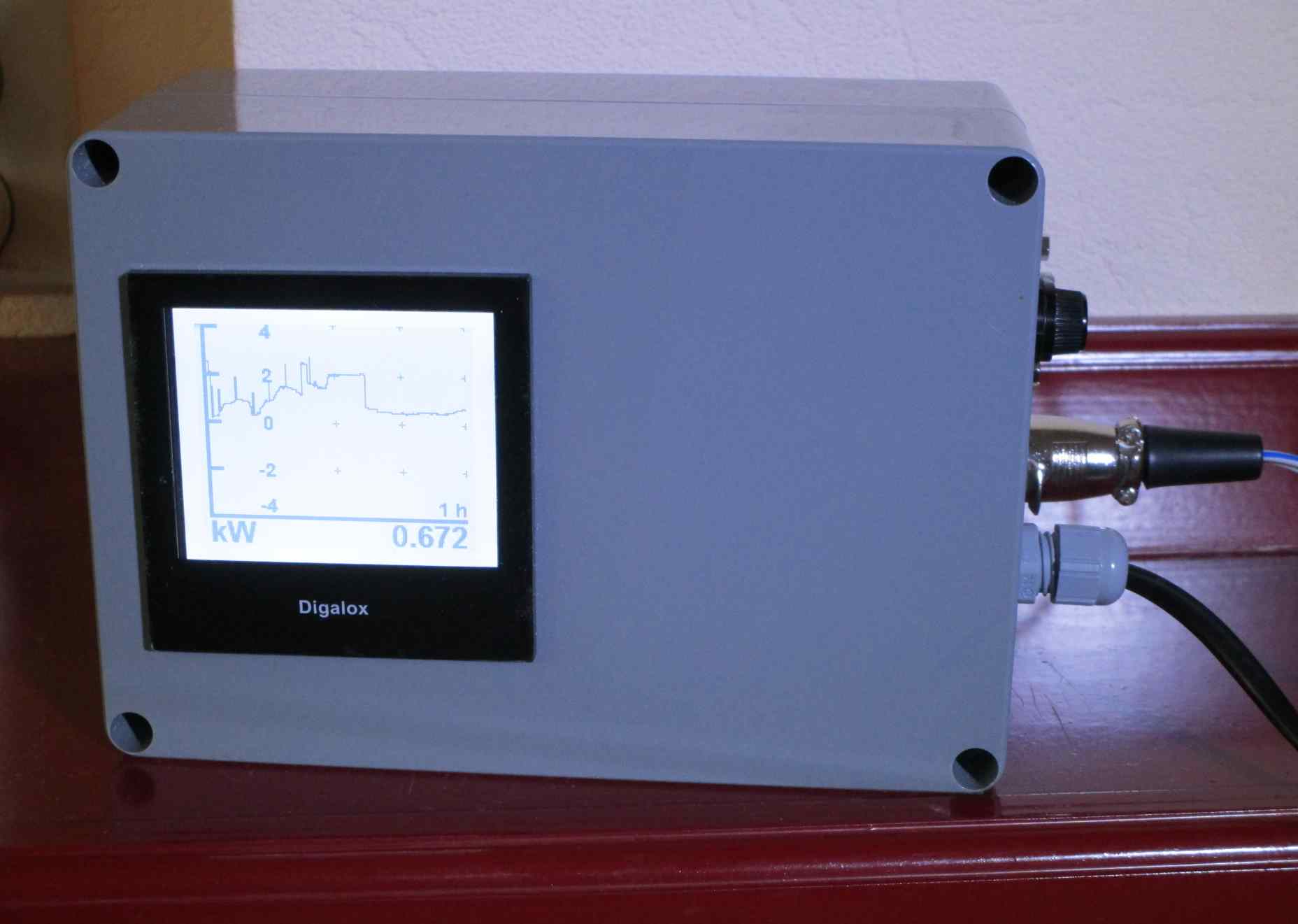
The power is shown on a graphical display which shows the data of the last hour.
Figure 1, the self made energy monitor.
The power measurement is very fast, about 1 second measuring time.
This circuit is designed for use with 230 to 240 Volt single phase mains
voltage, and maximum 50 Ampere current.
The circuit can drive a power dimmer, which can automatically turn on a load
(for instance an electric heater) if you have enough solar power.
This means that instead of exporting the power to the mains, you use it
yourself, and the power to the mains stays at about zero.
The circuit diagram.
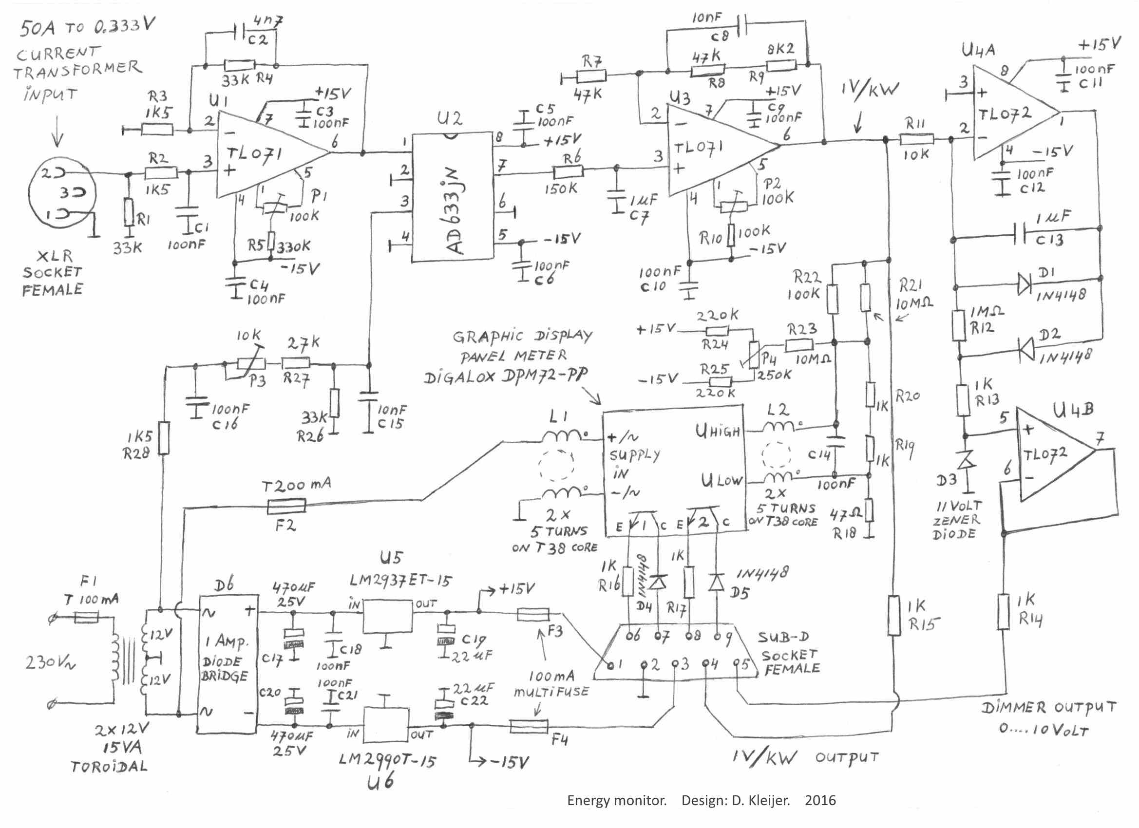
Figure 2, circuit diagram of the energy monitor.
The separate parts of the circuit diagram are discussed below.
Figure 3, the inside of the energy monitor, it all fits nicely in a 170 x 120
x 80 mm plastic box
The current transformer.
For measuring the current that is going in or out of the house, a split
core current transformer is used.
This transformer can be snapped around a wire, so there is no need to
disconnect the wire.
The voltage at the transformer output is proportional with the current through
the wire.
I use transformer model: SCT-0400-050 made by Magnalab (datasheet_SCT-0400.pdf).
This transformer is suitable for maximum 50 ampere AC current, in a frequency
range of 50 to 1000 Hz.
The output voltage is 0.333 Volt at 50 Ampere current.
I bought this current transformer at
Farnell.com (ordernumber 1797760).
Figure 4, The inside of my electrical distribution board.
On the right bottom side, you see the current transformer, snapped around the
wire going to the main switch.
All the current going in or out of the house, passes this wire.
You can snap it around the neutral wire, as I did (the blue one here in the
Netherlands), or you can snap it around the live wire (brown).
By the way, my house has a 35 Ampere single phase connection to the mains, however my
distribution board is prepared for 3-phase connection, so for instance it has
already a 4 pole main switch.
The cable from the current transformer is extended to about 12 metre, which runs
through the house to the energy monitor.
I used unscreened loudspeaker cable for this, and that works fine in my case.
If it runs at close distance parallel to live electrical wires, you might twist
the cable to prevent it from picking up to much interference, or
even better use screened cable.
The first amplifier.
The signal from the current transformer enters the energy monitor via a 3 pole
XLR socket.
The signal is then amplified by a TL071 operational amplifier.
The gain is determined by the value of R3 and R4, and is 1+ (R4/R3) = 1+
(33k/1k5) = 23.
With capacitors C1 and C2, the frequency range is set to 0 ... 1000 Hz.
Figure 5 , the first amplifier.
I used the TL071 because this one has inputs for offset compensation (pin 1 and
5) (datasheet_TL071_TL072_TL074.pdf).
And as we want to make an accurate energy monitor, we need to remove the op-amp
offset voltage.
Removing the offset is done as follows:
- Short circuit pins 1 and 2 of the XLR socket.
- Measure the voltage at pin 6 of the TL071.
- Turn potentiometer P1 to give a voltage reading of 0.000 Vdc
When measuring the maximum current of 50 Ampere (RMS), the current transformer
gives 0.333 Volt (RMS).
This is amplified 23 times by the first amplifier, so we get 7.659 Volt RMS, or
10.83 Volt peak at the output of the first amplifier.
The TL071 can deliver this without problem, and also the next stage can handle
this signal level.
Measuring the mains voltage. With the current transformer we have measured the mains current.
But the circuit also need to measure the mains voltage.
For safety reasons we don't directly measure the mains voltage, instead we use
the secondary voltage of the power supply transformer.
The secondary transformer voltage is proportional to the mains voltage.
Figure 6 , with this circuit we measure the mains voltage.
The input is connected to the 12 volt winding of the power supply transformer.
The 12 volt winding is actually giving about 13.5 volt, because we use the power
supply transformer only at 1/10 th of it's nominal power.
Capacitors C15 and C16 reduce the bandwidth of the signal to 1000 Hz, this
removes high frequency noise from the signal.
Also C15 and C16 provide a phase shift equal to the phase shift of the first
amplifier.
Now we need to adjust the output amplitude of this circuit.
- Measure the mains voltage.
- Multiply this by 0.03
- Measure the voltage across C15.
- Adjust potentiometer P3 to get across C15 the calculated value of 0.03 times
the mains voltage.
So, for instance when the mains voltage is 235 Volt RMS, you adjust the output
of this circuit to 7.05 Volt RMS.
Figure 7, this is the signal out of the voltage measure circuit, going to pin
3 of the AD633.
The frequency is 50 Hz (the period is 20 ms).
The peaks of the sine wave seems to be a little bit flattened, this is the actual shape of the
mains voltage here, it is not caused by the circuit or transformer.
The signal multiplier.
We now have a signal which represents the mains current.
And a signal which represents the mains voltage.
The next step is to multiply these two, and get a signal which represents the
power.
Figure 8, The AD633 is an analog multiplier (datasheet_AD633.pdf).
It is used here in the most simple form, with pins 2, 4 and 6 connected to
ground.
The output voltage (pin 7) is then equal to: 0.1 multiplied by voltage at
pin 1, multiplied by voltage at pin 3.
On both inputs (pin 1 and 3) we apply signals with 50 Hz frequency (or 60 Hz in
other parts of the world).
But on the output (pin 7) we get two other frequencies, namely 100 Hz, and 0 Hz.
A multiplier is in fact a frequency mixer, where you get at the output a sum
frequency (50+50=100 Hz), and a difference frequency (50-50=0 Hz).
Figure 9, an example of the voltage at the output (pin 7) of the AD633.
The power is positive (the DC component is above zero), for this picture I
snapped the current transformer around the wire going to an electric heater.
The frequency is 100 Hz (the period is 10 ms).
The power measurement should give a positive value if you use power.
If it gives a negative value, you should turn the current transformer or the
mains plug of the energy monitor by 180°.
The power value stays then the same, but the sign changes from - to + .
The output of the AD633 is followed by a 1 Hz low pass filter, consisting of R6 and
C7.
This passes the 0 Hz signal (DC voltage), but the 100 Hz signal is
strongly attenuated.
The DC voltage is proportional to the average power going in or out of the
house.
The voltage across C7 is positive when mains power is going into your house.
And the voltage across C7 is negative when you export power to the mains.
Capacitor C7 must by a 1 μF plastic film
capacitor, and for sure not an electrolytic one.
There are several types of the AD633, be sure to use the AD633JN, or the
AD633JNZ or the AD633ANZ (all have the letter N in the part number).
These are the ones in DIP package, which are the easiest to work with for the
hobbyist.
If you have one with the letter R in the part number, then the function of the
pins is different, and you should study the datasheet to connect it correctly.
Second amplifier The second amplifier is amplifying the DC signal from low pass filter
R6 /C7.
Figure 10, the second amplifier.
The gain of this amplifier is equal to: 1+ (R8+R9)/R7 = 2.1745
After you have adjust the offset of the first amplifier, you can adjust the
offset of this second amplifier.
- Short circuit pins 1 and 2 of the XLR socket.
- Measure the voltage at pin 6 of this TL071.
- Turn potentiometer P2 to give a voltage reading of 0.000 Vdc
- Remove the short circuit on the XLR socket.
Total gain of the circuit. Now we will calculate the gain of the circuit.
Let's say, to keep it simple, the mains voltage is 200 V, and the current 5
Ampere, so the power we measure is exactly 1 kW.
The current transformer gives 0.0333V at 5 Ampere.
The first amplifier has a gain of 23 times, so we get 0.0333V x 23=0.7659 V
The voltage measure circuit gives 200V x 0.03= 6V
The output of the AD633 will be: 0.1 x 0.7659 x 6 = 0.45954 V.
The second amplifier has a gain of 2.1745 and we get: 0.45954 x 2.1745 = 0.99927
V
So, the gain of the circuit is very close to 1 Volt per kW
The graphic display meter
For showing the results of the power measurement, I use a graphic display panel
meter.
It is model "Digalox DPM72-PP" made by TDE Instruments (datasheet_Digalox
DPM72-PP.pdf).
You can buy this meter at Conrad. (ordernumber: 1193747) .
I programmed the meter to show the values of the last hour on the display, but
you can also choose other timescales from 3 minutes to 14 days.
Figure 11, the connection of the Digalox DPM72-PP panel meter.
The maximum measuring range of the meter is plus and minus 60 mV.
And as we want to measure much higher voltages, I use a 1:100 voltage divider.
The top of the voltage divider is R22 parallel to R21, which is 99 kΩ.
The bottom of the voltage divider is R19+R20 (2 kΩ), parallel to the input
resistance of the meter which is also 2 kΩ.
This makes exactly a 1:100 voltage divider.
I had to add some components for suppressing interference, to get a correct and
stable reading of the last digit of the digital readout.
These components are:
- Resistor R18 which isolates the measure inputs slightly from ground.
- Capacitor C14
- Coils L1 and L2.
These both coils are wound on T38 Ferrite material ring cores (Farnell.com ordernumber: 1422737) , these cores
have 10.7 μH inductance for one turn.
But I use 5 turns, and that gives an inductance of 5²
x 10.7μH = 267 μH.
If you use other cores, try to get at least 100 μH inductance.
The two wires in the core are twisted together, and then looped trough the ring
core.
Figure 12, on this picture the blue ferrite core with coil L1 on it, and also
an overview of the settings on the backside of the panel meter.
When you connect a digital voltmeter to the 1V/kW output, it should give the
same reading as the kW reading of the graphic display panel meter.
But I noticed a small offset (about 0.012kW) caused by the graphic display panel
meter.
This offset can be compensated with potentiometer P4.
However, between + 40 Watt and -40 Watt the kW reading is always zero, maybe to
cover the small offset the panel meter has.
Therefore we cannot simply turn the reading to 0.000 to compensate for the
offset, because the reading stays 0.000 over quite a large range.
The adjustment to compensate the offset of the panel meter is as follows:
- Snap the current transformer on the wire of a load of about 100 to 200 Watt (I
used a 100 Watt light bulb).
- Measure with a digital voltmeter, the voltage on the 1 V/kW line, this should
be about 0.100 to 0.200 Volt (corresponding to the power of the load).
- Adjust potentiometer P4, to get the same reading on the graphic display panel
meter.
There are other models graphic display panel meters made by TDE Instruments, for
instance the Digalox DPM72-AVP.
That is an auto ranging voltmeter, I have tested this one also, but it could not
measure below 0.100 Volt, which is in this project equal to 100 Watt of power.
All power levels between -100 and + 100 Watts are displayed as 0.000 kW.
The DPM72-PP which I use now, can measure down to 40 Watt, and is for that
reasons better suitable.
Programming the graphic display panel meter.
Via the website of the
manufacterer TDE Instruments you can download the Digalox Manager,
this is configuration software for the panel meter.
With this software you can program the meter via an USB cable.
On the back of the meter is a row of dipswitches, which can all stay in the OFF
position, you don't need them if you use the software.
There is also a row of jumper pins, only one jumper is placed on position J1 to
select the timebase mode.
The next pictures show the settings I use in the Digalox Manager.
Figure 13, "Measurement settings" in the Digalox Manager.
In field "Caption 1" you can enter a text which appears in the lower left corner
of the display.
A second text can be entered in the field "Caption 2" which appears in the upper
right corner, but I don't use Caption 2 because that text is covering a part of
the diagram on the display.
The upper and lower part of the scale are set to + 4 and -4 (kW).
More then 99% of the time, the power levels I measure are between these limits.
And if the power level is outside this range, the line in the graph is limited
to +4 or -4, but the digital readout in the lower right corner is still showing
the correct value.
If the power level is outside plus or minus 6800 Watt, the limit of the
digital readout is reached, and the display shows: "out of range".
The "upper display value" is the value which must be displayed with 60 mV on the
input of the meter.
And as I use a 1:100 divider, 60mV on the meter corresponds to 6 Volt before the
divider, which means 6 kW power.
So in the field "upper display value" I put the number 6.
If you use (for instance) a 1:150 voltage divider, you should place "9" in the field "upper
display value" and up to 9 kW (in practice even something more) could be
measured.
But then there is one digit less in the digital readout, so the resolution of
the readout is 10 watt.
I rather have a 1 Watt resolution, for this reason I use a 1:100 Voltage
divider, and keep the upper display value at "6".
If the measurement of power is between +40 Watt and -40 Watt, the meter shows
always 0.000.
But the higher you set the "upper display value", the larger is the range where
the meter shows 0.000, so that is another reason for not increasing the upper
display value.
Figure 14, "General settings" in the Digalox Manager.
Here you can select the timebase value from 3 minutes to 14 days.
The "decimal places" are set to "one more" , this gives the maximum number of
digits in the digital readout.
Figure 15, "Threshold settings" in the Digalox Manager.
The meter has two transistor outputs, which can be programmed here to switch on
and off at certain measuring values.
I wired the transistor outputs to the pins of a sub-D connector for future use,
but at the moment I don't use these threshold settings.
Dimmer driver circuit.
The next part of the circuit is a driver for a dimmer.
It is for use in combination with a dimmer with a 0 ... 10 Volt input.
If your solar panels generate enough power, the excess energy will normally be
fed into the mains.
But this circuit turns automatically on a power dimmer when there is enough
energy.
The dimmer can drive for instance a heating element, to warm your house or to
warm a vessel of water for later use.
The result is, that the power into the mains stays at about zero.
Figure 16, dimmer driver circuit.
If you use power from the mains, the 1V/kW signal has a positive value.
Then diode D1 will conduct, and D2 will block, and the dimmer output stays at 0
Volt.
If you start feeding power into the mains, the 1V/kW signal becomes negative.
Then diode D1 will block, and D2 will conduct, and by the combination of R11
(10kΩ) and R12 (1MΩ) the signal is amplified 100
times.
The driving signal to the dimmer is limited to maximum 11 Volt by zenerdiode D3.
To drive the dimmer fully open, you need 10 Volt driving signal, the 1V/kW
signal is then 10V/100 = 0.1 Volt, which means your solar panels feed 100 Watt
into the mains.
So, actually this circuit does not keep the power into the mains at exactly zero, but
somewhere between 0 and 100 Watt.
Figure 17, The NS 80 dimmer may be loaded up to 2200 Watt, in this picture, it
is driving a 1500 Watt electric heater.
Note: The FG-Elektronik NS 80 dimmer is now obsolete.
An alternative is the Kemo M240 Power Controller, for sale at Conrad
Conrad ordernumber 2164500 .
Datasheet: datasheet_Kemo_M240.pdf
I have not tested the Kemo M240 myself, but it should work probably as
well as the NS 80.
However it needs to be mounted on a heatsink.
And it has no build in power line filter, which the NS 80 dimmer has.
Kemo M240.
Power supply circuit.
The next circuit provides +15Volt and -15Volt for the energy monitor.
Figure 18, power supply for the energy monitor.
A toroidal transformer is used, because these have very low power consumption
(more info about this subject, on
this page ).
The power consumption of the energy monitor with the display light on, is about
1.6 Watt.
The LM2937ET-15 (datasheet_LM2937.pdf ) and
the LM2990T-15 (datasheet_LM2990.pdf ) are
low drop voltage regulators.
The inputs of the regulators are at about +18 and - 18 Volt.
The transformer also provides the power for the panel meter, and the voltage
signal for the voltage measure circuit.
These two functions are connected to the opposite windings, so
the power consumption of the panel meter has not to much influence on the
measurement of voltage.
Sub-D output connector.
There must be an output for the 0 ... 10 Volt signal to the dimmer.
But I thought it might be in the future useful to have some other signals
available at the output connector.
These are:
- The +15 Volt and -15 Volt.
- The 1V/kW signal.
- The two programmable transistor outputs of the panel meter.
Figure 19, The Sub-D output connector with its functions.
With resistors and fuses the outputs are made "short circuit proof".
At the moment, I only use the signals from pins 2 and 5 to drive the dimmer.
Figure 20, here you see what happens if you turn on the dimmer.
In the last part of the diagram, the dimmer is turned on, and the
export of power to the mains reduces to almost zero.