Complex impedances
With the next calculator, several properties are calculated for a series
circuit build with a resistor and a coil or capacitor.
Enter the frequency, resistor and coil / capacitor value in the yellow coloured
fields, and click on
"calculate".
Below is explained what this calculator is calculating.
What is impedance
Impedance is a kind of resistance value which an electrical component seems
to have at a certain frequency.
The impedance is indicated with the letter X, the unit is
Ω (Ohm).
For a resistor is the impedance: X=R
For a coil is the impedance: X=2.pi.f.L
For a capacitor is the impedance: X= 1/(2.pi.f.C)
X = impedance (Ω)
pi =3.1415
f =frequency (Hertz)
L = induction of the coil (Henry)
C = capacity of the capacitor (Farad)
This way of describing the impedance is however not complete, because the
phase between voltage and current is not shown.
From the value X, we can't see if it is a resistor, coil or capacitor.
Complex impedance
A complex impedance is build up with a real part (R=resistor) in series with a
imaginary part (+JX = coil or -JX = capacitor).
A complex impedance is indicated with the the letter Z, and the unit is
Ω.
The notation of a complex impedance can be Z=R+JX.
In this case a resistor and coil are series connected.
The impedance of the coil is: X=2.pi.f.L
With a coil, the (alternating) voltage will always run 90° ahead of the current,
this is indicated with +J.
The notation for complex impedance can also be: Z=R-JX.
In this case a resistor and capacitor are series connected.
The impedance of the capacitor is X= 1/(2.pi.f.C)
With a capacitor, the (alternating) voltage will always run 90° behind the
current, this is indicated with the -J.
Example 1: Z1=220+J300 Ω.
In this example a resistor of 220 Ω
and a coil with a impedance of 300 Ω
are series connected.
These two components in serie make one complex impedance.
Example 2: Z2=470-J80 Ω
In this example a resistor of 470 Ω
and a capacitor with an impedance of 80 Ω
are series connected.
Example 3: Z3=100+J0 Ω
This is a pure resistor of 100 Ω (at that
frequency).
Because the imaginary part is zero, we can also write : Z3=100-J0
Ω
Example 4: Z4= 0+J60
Ω
This is a coil with a impedance of 60 Ohm, this coil has no series
resistance.
Example 5: Z5=0-J400 Ω
This is a capacitor with an impedance of 400
Ω, this capacitor has no series resistance.
The J operator
The letter J in complex impedances is called the J operator.
In a resistor the voltage across the resistor and the current through it are
in phase, there is no phase difference.
The impedance of a resistor is called a real impedance.
The impedance of a coil is not real but imaginary.
In a coil, the voltage always runs 90° ahead of the current, this is indicated
by +J followed by the impedance value.
A capacitor is also a imaginary impedance.
In a capacitor the voltage runs always 90° behind the current, this is indicated
with -J followed by the impedance value.
Calculating with the J operator
If we are calculating with imaginary impedances, the following rules apply:
J = √-1
J² = -1
1/J = -J
1/-J = J
Ja + Jb = J(a+b)
J-a = -Ja
Adding complex impedances
If two complex impedances are series connected, a new complex impedance
is formed.
When adding two complex impedances, we can add the real parts, and also add the
imaginary parts.
Example: Z1 and Z2 are series connected, the sum of these two is Z6.
Z1=220+J300 Ω
Z2=470-J80 Ω
+
Z6=690+J220 Ω
The imaginary parts are added, but because the imaginary part of Z2 is
negative, it is in fact subtracted from the imaginary part of Z1.
Another example: Z7=Z1+Z2+Z3+Z4+Z5
Z1=220+J300 Ω.
Z2=470-J80 Ω
Z3=100+J0 Ω
Z4= 0+J60 Ω
Z5= 0-J400 Ω
+
Z7=790-J120 Ω
The sum of all these impedances behaves on that frequency the same as a
resistor of 790 Ω is series with a capacitor with
120 Ω impedance.
Resonance
If a capacitor and coil are series connected, and the imaginary parts are equal,
they will add to zero Ω.
The circuit then is in series resonance, and only the resistance of both
components is left.
In series resonance, the impedance of the LC circuit will reach the lowest
value.
With parallel LC circuits, the impedance will reach the highest value at resonance.
The Q factor
We can calculate the quality factor (Q) of a complex impedance.
The Q ratio between imaginary part and real part of the impedance.
Q=X/R
It doesn't matter if the imaginary part is positive or negative, in the
calculation we only use the number behind the J.
The Q has no unit, and the value is always positive (or zero, in case of a pure
resistor).
Example: Z7=790-J120 Ω has an Q of 0.1519
The absolute value of the impedance
If we connect an alternating voltage to the complex impedance, a current will
flow.
To calculate the value of the current, we need to know the absolute value of the
impedance.
The absolute value is indicated with |Z| and the unit is
Ω.
For an complex impedance Z=R±JX is the absolute value:
|Z| = √(R² + X²)
Example: Z7=790-J120 Ω
|Z7| = √(790² + 120²) = 799 Ω.
If this impedance is connected to alternating voltage, a current will flow with
the value:
I = U / |Z|
Example: the voltage across Z7 is 10Volt RMS.
|Z7|= 799 Ohm
I=10 / 799 = 0.0125 Ampere RMS.
Phase between voltage and current
The phase between the voltage across the complex impedance and the current
through it can be calculated as follows:
Phase = arctangens (±X/R).
The unit is degrees ( ° )
The X value can be both positive or negative, according to the sign before
the J operator.
With a positive value for phase, voltage runs ahead of the current.
With a negative value for phase, voltage runs behind the current.
The value for phase can vary from +90° (coil), via 0° (resistor) to
-90° (capacitor).
Example:
With a complex impedance of Z7=790-J120 Ω
the phase between voltage and current is:
Phase= arctangens (-120 / 790) = -8.6°
Impedances as vectors
Complex impedances can be placed as vectors into a diagram.
The angle with the horizontal axis indicates the phase between voltage and current, the length of the vector corresponds to the value of the impedance.
|
|
|
|


 A complex impedance: Z8=4+J3 Ω The length of vector Z8 is equal to the absolute value |Z8|. In this case: |Z8|=√(4²+3²)= 5 Ω |
 Two complex impedances (Z8 and Z9) are series connected. Z10 is the sum of Z8 and Z9, so Z10=Z8+Z9 |
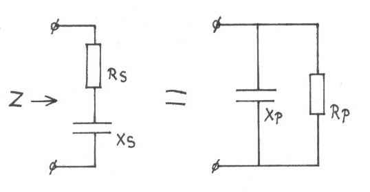
Converting series impedance to parallel impedance
A complex impedance consisting of a resistor in series with a coil / capacitor
can be converted into a parallel circuit of a resistor and a coil / capacitor.
Both circuits will behave completely the same on that frequency, but this is
only true for one frequency at which we calculate the circuit.
 |
A series circuit of resistor and coil is converted into a parallel circuit of resistor and coil. |
 |
A series circuit of resistor and capacitor is converted into a parallel circuit of resistor and capacitor. |
The conversion works as follows:
We have the complex series circuit Z=RS+JXS
RS and XS are the series
components.
With the next formulas we can find the values for the parallel components RP
en XP.
Rp = (RS²+XS²)/RS
Xp = J(RS²+XS²)/XS
When the complex impedance is capacitive, so Z=RS-JXS
then also the value of XP will be negative.
Example1:
The complex impedance is Z=20+J15 Ω
The parallel impedances are:
RP = (20²+15²)/20 = 31.25 Ω
XP = J(20²+15²)/15 =
+J41.67 Ω
A series circuit of resistor and coil is converted into a parallel circuit of
resistor and coil
Example2:
The same component values, but now for a capacitive impedance
The complex impedance is Z=20-J15 Ω
The parallel impedances are:
RP = (20²+(-15)²)/20 = 31.25
Ω
XP = J(20²+(-15)²)/-15
= -J41.67 Ω
A series circuit of resistor and capacitor is converted into a parallel circuit
of resistor and capacitor.